When connecting two objects by calling pXcon_add, make sure that they are already in the right position and don't penetrate each other. If they are meant to penetrate a little, set both objects to the same group ID using pXent_setgroup.
Joints can be made breakable. If a breakable joint is tugged on with a large enough force, it will snap apart. An example for this is a factory chimney divided into sections, each section held together with a joint that is locked on all axes. When the chimney is hit, it will break apart and topple over by sections rather than unrealistically falling over in one piece.
Wheel joints and 6D joints can be equipped with a suspension/damper element and motors that apply torque to an axis, thus allowing for the realistic modeling of vehicles or other machinery.
The available joints are listed below with their required parameters:
| Type: | |
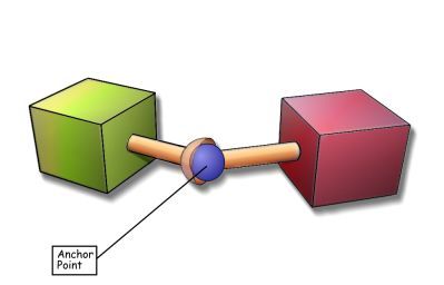
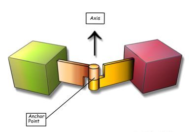
| Description : | A hinge constrains two entitites to have a common axis of rotation and to stay a fixed distance from this axis. As depicted in the image above, you need to specify this rotation axis and an anchor point on said axis. The distance from each entity to the axis is determined when you first create the constraint. Therefore make sure to place the entities in the right position, before adding the hinge. The initial orientation is also taken as an angle value of zero degrees. Thus if both entities are rotated by 90 degrees with respect to each other and you set the angle limit to (0,0) they will remain in the initial orientation. |
| Parameter 1 : | Anchor point in world coordinates (default: middle position between the two entities). |
| Parameter 2 : | Hinge axis direction vector in world coordinates (default: 0,0,-1). |
| Parameter 3: | Break limits. The x parameter sets the maximum force and the y parameter sets the maximum torque. If any of those values are exceeded, the joint will break. |
| Parameter 4 : | Allowed angles, e.g. (-45, 90, 0) sets the lower limit to -45 degrees and the upper limit around the axis to +90 degrees. Use (-360, 360, 0) to remove all limits. The z value gives the joint restitution factor in percent. |
| Parameter 5 : | Not used. |
| Parameter 6 : | Not used. |
| Type: | |
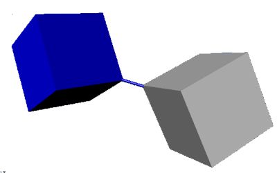
| Description : | Description: Entities rotate freely around the balljoint/anchor point. This type of joint can also be used for chains or ropes. |
| Parameter 1 : | Anchor point in world coordinates (default: middle position between the two entities). |
| Parameter 2 : | Not used. |
| Parameter 3: | Not used. |
| Parameter 4 : | Not used. |
| Parameter 5 : | Not used. |
| Parameter 6 : | Not used. |
| Type: | |
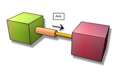
| Description : | Entities are allowed to rotate along the slider axis and move along the slider axis. Other movement is blocked. |
| Parameter 1 : | Not used. |
| Parameter 2 : | Slider axis direction vector in world coordinates (default: 0,0,-1). |
| Parameter 3: | Break limits. The x parameter sets the maximum force and the y parameter sets the maximum torque. If any of those values are exceeded, the joint will break. |
| Parameter 4 : | Allowed distance from original position, e.g. (-100, 1000, 0) allows the objects to slide apart by 1000 quants along the axis and 100 quants in the opposite direction, thus giving a total range of 1100 quants. |
| Parameter 5 : | Not used. |
| Parameter 6 : | Not used. |
| Type: | |
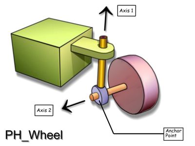
| Description : | This is not a real joint, but adds a motorized wheel shape to a vehicle entity. Wheels are allowed to rotate around axis 1 and axis 2. Axis 1 is the steering axis (left/right), while axis 2 is used for forward/backward movement. Because the wheel entity is not an actor, but a shape, it must not be registered as a physics entity. Use pXcon_setwheel for applying a steer angle and a motor torque, and pXcon_setparams2 for modifying the wheel friction curve dependent on the state of the car and the road. |
| Parameter 1 : | Anchor point direction vector in world coordinates. |
| Parameter 2 : | Wheel axis 1 relative to the chassis (default: 0,0,-1). |
| Parameter 3: | Wheel axis 2 relative to the wheel´s orientation (default: 1,0,0). |
| Parameter 4 : | Not used. |
| Parameter 5 : | x = wheel longitudinal friction curve scale factor in percent (default = 100). |
| Parameter 6 : | x = wheel suspension spring constant (default: 1000). Adjust this to the car mass and gravity. y = wheel suspension damper constant (default: 100). z = wheel suspension way in quants (default: wheel radius). |
| Type: | |
| Description : | The rope constraint tries to maintain a certain minimum and/or maximum distance between two points attached to a pair of entities. It can be set to springy in order to behave like a rubber band. An example for a rope joint is a pendulum swinging on a string; another example is the pX_pick function that attaches a rubber band between the mouse and the clicked object. |
| Parameter 1 : | Anchor point on the first entity, in entity coordinates (default: origin). |
| Parameter 2 : | Anchor point on the second entity, in entity coordinates (default: origin). |
| Parameter 3: | Break limit. The x parameter sets the maximum force and the y parameter sets the maximum torque. If any of those values are exceeded, the rope will break. |
| Parameter 4 : | Not used. |
| Parameter 5 : | Not used. |
| Parameter 6 : | x = rope spring constant. Set this to 0 for a non elastic rope. y = rope minimum distance. Set this to 0 for no minimum distance. z = rope maximum distance (default: initial distance between entities). |
| Description : | The mother of all joints - a configurable, motorized joint with up to 6 degrees of freedom. This joint type can be configured to model nearly any joint imaginable. The joint motion is set to NX_D6JOINT_MOTION_LOCKED for all axis as default value; you can change that with pXcon_set6djoint afterwards. Details about the PH_6DJOINT parameters can be found in the PhysX SDK documentation. |
| Parameter 1 : | Anchor point in world coordinates (default: middle position between the two entities). |
| Parameter 2 : | Joint axis direction vector in world coordinates (default: 0,0,-1). |
| Parameter 3: | Break limits. The x parameter sets the maximum force and the y parameter sets the maximum torque. If any of those values are exceeded, the joint will break. |
| Parameter 4 : | Swing angle limits in degrees. The x parameter sets the pan limit and the y parameter sets the tilt limit. |
| Parameter 5 : | Twist angle lower and upper limits in degrees, e.g. (-45, 90, 0) sets the lower limit for rolling about the joint axis to -45 degrees, and the upper roll limit to +90 degrees. |
| Parameter 6 : |
x = spring constant, causes a backwards force when the joint moves beyond its limit. y = damper constant, resistance against movement beyond the limit. z = linear limit for movement along the joint axis. |