Workshop 6: Shadow Mapping
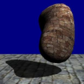
Shadows not only add realism and atmosphere to a scene. They are also an important visual cue that gives information about the relative positions of objects in the scene. Shadow volumes and shadow mapping are the two most common algorithms used by 3D engines for rendering shadows in real time. Shadow volumes do not require shaders at all, and are already used by the engine's built-in stencil shadow algorithm. But we'll here concentrate on shadow mapping. Both methods can generate hard-edged as well as soft-edged shadows, but on high-end 3D hardware the advantages of shadow mapping outweigh its disadvantages. It is a more 'natural' approach to shadows and avoids the typical stencil shadow artifacts, such as the 'ghost shadows' on the far side of objects. Its frame rate impact, although high at first, is not as dependent on the number and complexity of objects as with stencil shadows. With shadow mapping, all objects in the level can be shadow casters, shadow receivers, and self-shadowing at the same time.
Despite the high respect many developers have of shadow mapping, a basic shadow mapping shader is simple - much simpler than most shaders you've already got to know from the previous workshops! The idea is to determine for every pixel on the screen whether it's in shadow or not, and paint it darker or brighter depending on that. For this we could cast a ray from the pixel to the light source. If an obstacle is in the way, the pixel is in shadow. This is the method used by WED's map compiler to calculate static shadows, but it is too slow for today's rendering hardware. So how can we map shadows in real time?
Practical shadow mapping
Fortunately, there's a trick for knowing if a pixel is in shadow or not. Before rendering the scene, we render it in a pre-processing step with the camera at the position of the light. This generates the scene 'as the light sees it'. All surface pixel that are visible from the light position can not be in shadow. Therefore we know that all other surface pixels must be in shadow. Simple, huh?
But how can we transfer that information to the real rendered scene? If would be easy if we could somehow mark all surface pixels that are reached by the light, but that's beyond our memory capacity. Instead, we just store the light distance of each illuminated pixel in a depth buffer. When rendering the real scene, we calculate the distance of any rendered pixel to the light position. If this distance is equal to the stored depth at that pixel position, we know that the same pixel was visible from the light and thus is illuminated. If the distance is higher, we know this pixel was not stored in the depth buffer, was therefore not visible in the light scene, and is in shadow.
Thus practical shadow mapping requires two steps (at least):
1 |
Render the scene from the light position. Store the light distance of all illuminated pixels in a depth buffer. |
 |
|
2 |
Render the scene from the camera position. Compare the light distance of any pixel with the depth buffer value at that position.
If the pixel's light distance is above it's depth buffer value, paint the pixel dark; otherwise, paint it bright. |
 |
The 'at least' above refers to the fact that usually additional steps are used for antialiasing and blurring the shadows before projecting them finally onto the scene. We'll deal with that in the next workshop, but skip that here as we want to keep this workshop as simple as possible.
The Depth Shader
So we now have two different shaders: The depth buffer generating shader of the first step, and the distance-comparing shader of the second step. Let's look at the depth shader first (depth.fx):
// Application fed data:
const float4x4 matWorldViewProj;

// Vertex shader:
void DepthVS (in float4 InPos	: POSITION,
				out float4 OutPos : POSITION,
				out float OutDepth: TEXCOORD0)
{
// Output the transformed vertex position
	OutPos = mul(InPos,matWorldViewProj);
// Output the vertex depth
	OutDepth = OutPos.z;
}

float4  DepthPS( in float InDepth: TEXCOORD0 ) : COLOR0
{
// Output the pixel depth to a R32 floating point texture
	return float4( InDepth, 0.0, 0.0, 1.0 );
}

technique techDepth
{
	pass p0
	{
		Lighting	= False;
		VertexShader = compile vs_2_0 DepthVS();
		PixelShader  = compile ps_2_0 DepthPS();
	}
}
This is pretty straightforward: the vertex shader outputs the pixel distance from the screen, which is nothing else but its transformed z coordinate. The pixel shader just takes the distance and outputs it into the red color component, which is stored in a R32 floating point texture. A floating point texture, unlike a normal texture, can hold values in a floating point format that greatly exceeds the 0.0..1.0 range of normal color values. "R32" means that the texture holds one 32 bit floating point variable per pixel in its red channel, which is the reason why the depth values are painted red in the small image above.
The Shadow Shader
Once we've stored the depth values, the scene is rendered. Here's our distance-comparing-and-shadowing shader, shadow.fx:
//Tweakables
static const float fDark = 0.3;
static const float fBright = 1.0;
static const float fDepthOffset = 0.95;

// Application fed data:
const float4x4 matWorldViewProj;	// World*view*projection matrix.
const float4x4 matWorld;	// World matrix.
const float4 vecSunDir;	// Sun direction vector.
const float4x4 matMtl; 	// Texture projection matrix

texture TargetMap;
texture entSkin1;
sampler DepthSampler = sampler_state { Texture = <TargetMap>; };
sampler TexSampler = sampler_state { Texture = <entSkin1>; Mipfilter = Linear; };

// Shadow mapping vertex shader
void ShadowVS (in float4 inPos: POSITION,
		in float2 inTex: TEXCOORD0,
		in float3 inNormal: NORMAL,
		out float4 outPos: POSITION,
		out float2 outTex: TEXCOORD0,
		out float3 outNormal: TEXCOORD1,
		out float4 outDepth: TEXCOORD2)
{
// Transform the vertex from object space to clip space:
	outPos = mul(inPos, matWorldViewProj);
// Transform the normal from object space to world space:
	outNormal = normalize(mul(inNormal,matWorld));
// Pass the texture coordinate to the pixel shader:
	outTex = inTex;
// Output the projective texture coordinates
	outDepth = mul( mul(inPos,matWorld), matMtl );
}

// distance comparison function
float fDist(float4 DepthCoord,float fDepth)
{
	return tex2Dproj(DepthSampler,DepthCoord).r < (fDepth*fDepthOffset)? fDark : fBright;
}

// Shadow mapping pixel shader
float4 ShadowPS (in float2 inTex: TEXCOORD0,
		in float3 inNormal: TEXCOORD1,
		in float4 inDepth: TEXCOORD2) : COLOR0
{
// Calculate the diffuse term:
	float fDiffuse = saturate(dot(-vecSunDir, normalize(inNormal)));

// Calculate the shadow term
	float fShadow = fDist(inDepth,inDepth.z);

	return tex2D(TexSampler,inTex) * fShadow * fDiffuse;
}

technique techShadow
{
	pass p0
	{
		VertexShader = compile vs_2_0 ShadowVS();
		PixelShader  = compile ps_2_0 ShadowPS();
	}
}
We already know most of the stuff from the previous shaders. The only new variable outDepth is passed by the vertex shader passes to the pixel shader for looking up the depth values from the depth map. We can not directly compare a pixel with the depth value at the same screen position. The light view and the camera view were rendered from different locations, so a pixel position in the depth map is different from the screen position of the same pixel in the camera view. For comparing the distances we must first transform the pixel positions into the coordinate system of the light view. This is done through the matMtl transformation matrix that was precalculated from the light view's World*View*Projection matrix.
This is our distance comparison function that is called by the pixel shader:
float fDist(float4 DepthCoord,float fDepth)
{
	return tex2Dproj(DepthSampler,DepthCoord).r < (fDepth*fDepthOffset)? fDark : fBright;
}
HLSL allows us to define functions just like lite-C. But unlike in lite-C, those functions are not really called; the HLSL compiler just puts them at the appropriate places into the shader code. So they look like functions, but are in fact macros. The fDist function takes the depth map lookup coordinate (DepthCoord) that was precalculated by the vertex shader, retrieves the depth value (a floating point value out of the red channel) and compares it with the pixel's light distance (fDepth) multiplied with an offset factor. We're using the tex2Dproj shader function that divides the .x / .y texture coordinates by the .w coordinate before retrieving the texture content - this is equivalent to a projection transformation. If the pixel distance to the light is greater than the retrieved depth value, the function returns fDark, otherwise fBright.
float4 ShadowPS (in float2 inTex: TEXCOORD0,
		in float3 inNormal: TEXCOORD1,
		in float4 inDepth: TEXCOORD2) : COLOR0
{
// Calculate the diffuse term:
	float fDiffuse = saturate(dot(-vecSunDir, normalize(inNormal)));

// Calculate the shadow term
	float fShadow = fDist(inDepth,inDepth.z);

	return tex2D(TexSampler,inTex) * fShadow * fDiffuse;
}
The pixel shader first calculates our standard diffuse lighting and then calls fDist for multiplying the final color with a dark or bright value, dependent on whether the pixel is in shadow or not. Note that we're using here the z component of the depth coordinate for the pixel distance. Because the matMtl matrix is basically the WorldViewProj matrix of the light view, the transformed z coordinate is just the distance of the vertex to the light.
We multiply the distance with the fDepthOffset factor to avoid aliasing artifacts that are caused by comparing two different distance curves. The pixel shader performs linear interpolation between the vertex distances, while the depth map distance curve is not linear between the projected vertex positions. This results in a difference of real and mapped distances between vertices and causes jagged edges for the shadows. There are several standard methods to overcome this problem, like filtering the depth map values with a PCF (percentage closer filtering), using a different coordinate system for the depth map (perspective shadow mapping) or better approximating the distance curve (variance shadow mapping). Here we're just covering the mess with the merciful darkness of diffuse shading, and with a generous depth offset factor that makes the curves more 'steep' and less sensible to distance differences.
Run shadowdemo.c:
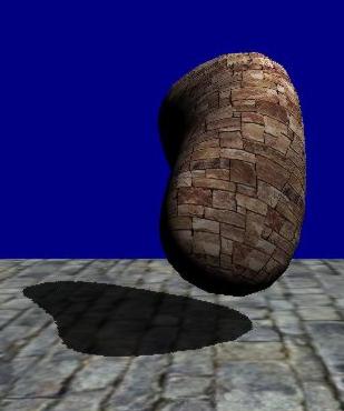
We've just learned how to create shadows with only a few lines of code. However, the shadow doesn't really look better than the stencil shadows of the engine. In fact it looks worse. Even though we got rid of the worst distance-difference jaggies, we still have the aliasing staircase effect at the shadow edges. This effect results from the low resolution of the transformed shadow map, compared to the resolution of the surface textures. In the next workshop we'll learn how to take care of that.
Next: Soft Shadows